I’ve been working to improve the look and feel of a couple of my Bally / Stern favourites. After a couple of attempts over the past two years, I have a finally settled on an LED with a “neutral” colour temperature.
After a considering the benefits of making LED inserts in Warm and Cool configuration, I am very happy with the colour clarity given by the LEDs in the “Neutral” territory. The LEDs I have used have a CCT reference range of 4910K~5120K. These allow a good colour presentation inside green and blue inserts without making the colours too blue (as I feel cool LEDs can do).
The PLCC-2 package show an even light distribution without harsh spotting.
The boards are made with v-cut edges and can be separated into individual items easily by hand.
With the advent of repaired or replaced Solenoid Driver boards (SDB) some people experience an unreliable “reset” on their original Bally or Stern MPU board. I hope to describe here a cause and remedy for this situation.
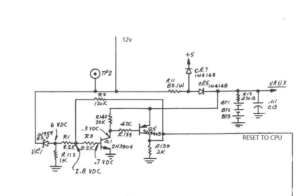
Valid Power vs Reset. At the heart of the problem is the intention of the circuit shown above. Its functionality is to hold the CPU in reset (high) until the power supply reaches a “valid power” state. This is a fundamentally fine objective, but it conflicts (somewhat) with the requirements of CPU reset requirements.
The CPU requires the reset line to be held low for at least 8 clock cycles after 5v power rail has reached 4.75v.
Inspecting the Bally Stern circuit, we see no capacitors in the design to enforce the minimum time needed in reset. The reset signal is held low until the 12volt rail exceeds 8 volts. The designers have assumed a steady ramp up of the 12 volt supply rail and a fast stabilisation of the 5 volt regulator will provide sufficient “Reset low” time for the CPU. Indeed they are assuming a precise relationship between the 12volt ramp-up time and the speed of the 5 volt regulator.
With modern replacement regulators, new power supply capacitors, switch mode power supplies and the likes, the precise timing of the reset circuitry can no longer be guaranteed.
Resolution
Install a dedicated reset management chip like the Dallas DS1811.
These reset chips include both a valid power detection circuit and a timing element to ensure the reset line is held low for a minimum of 150mS after a valid-power condition.
Installing DS1811-10
Installing a DS1811-10 is relatively simple on the Stern MPU-100 and AS-2518-17.
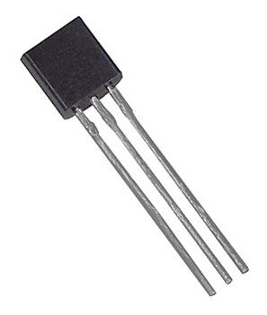
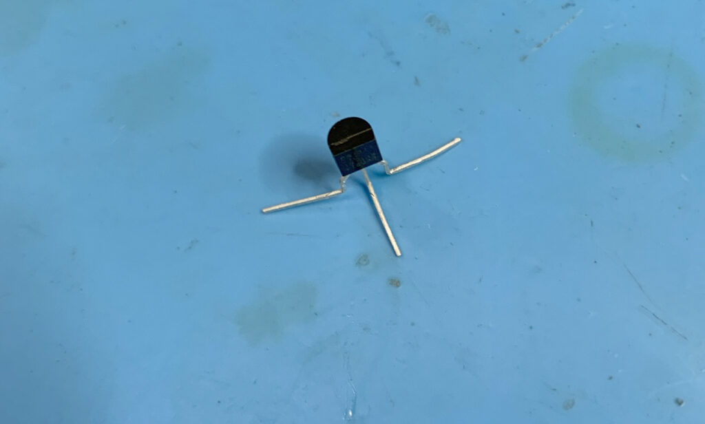
The DS1811-10 is a 3 pin package (TO-92) that resembles a transistor. It can be installed onto the MPU board easily requiring requiring the removal of only three components from the original circuit.
Step 1:
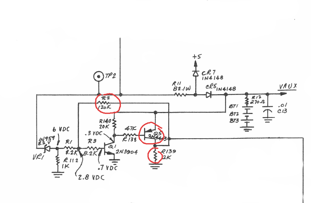
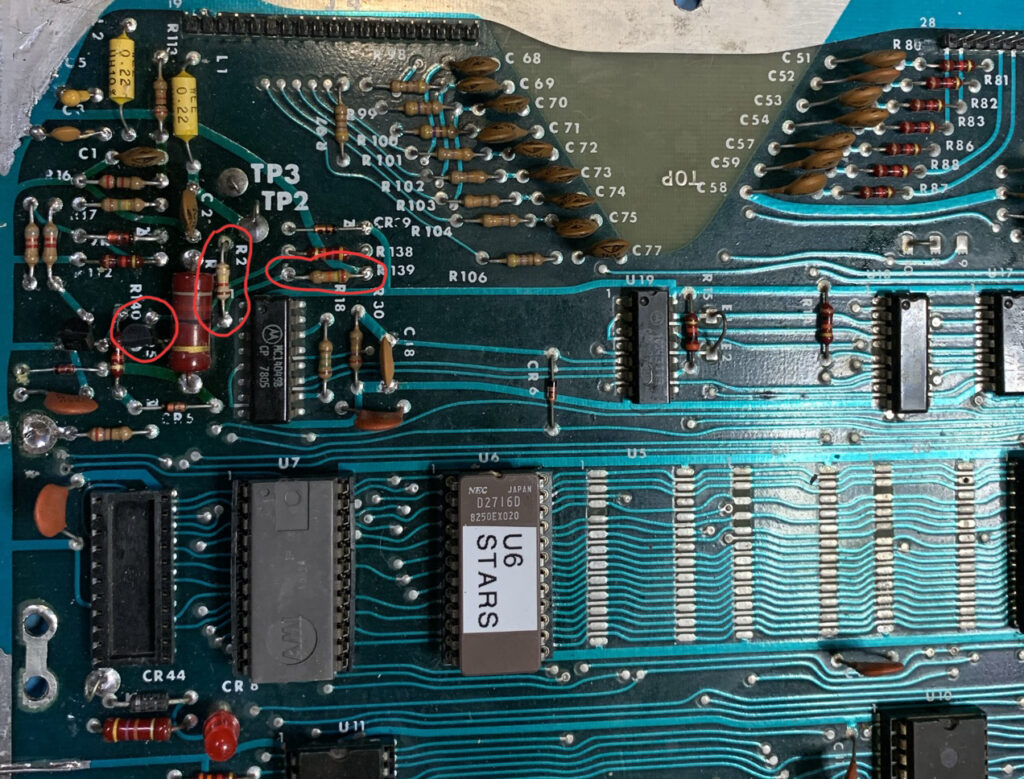
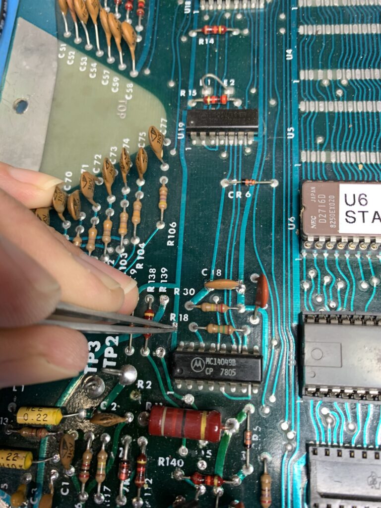
Remove resistors R2 and R139. They may be removed with a soldering iron or just snipped from the top side of the board.
Step 2:
Remove transistor Q5. Use either a soldering iron or merely snip the legs from the top side of the board.
Step 3:
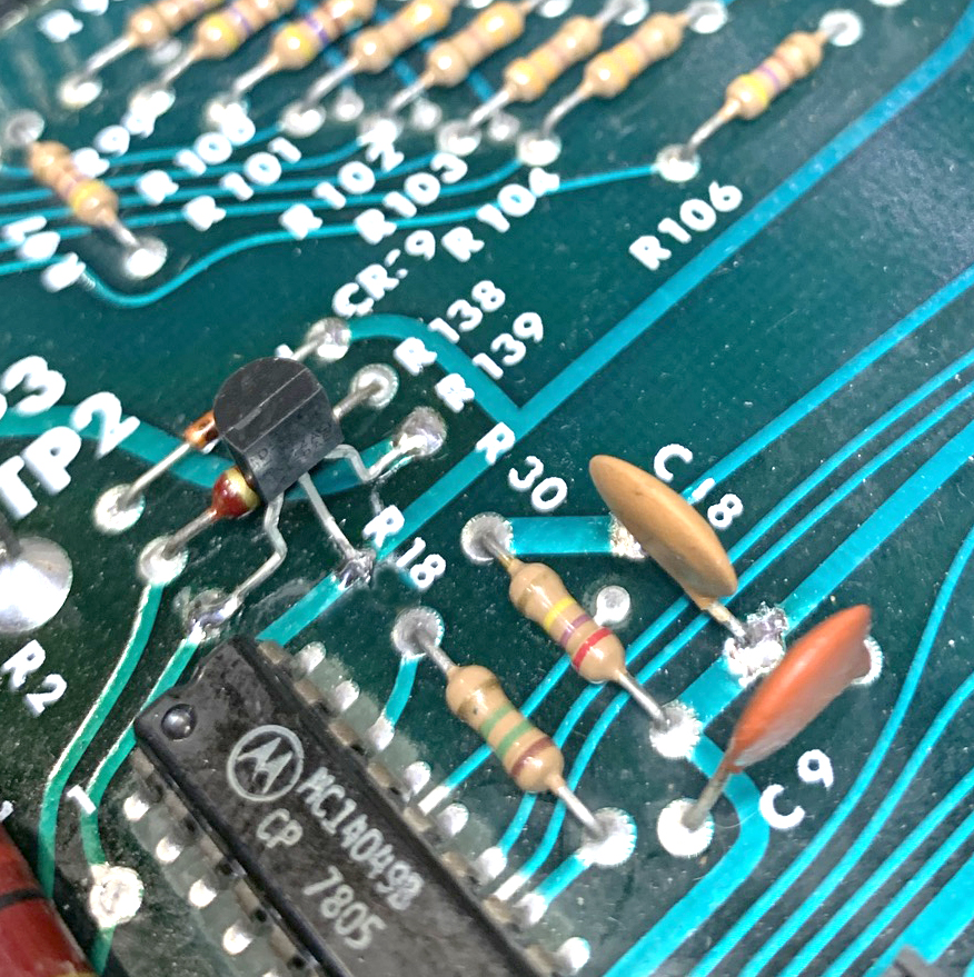
Scrape a section of the solder resist away from the tract near R139. (See photo)
Step 4:
Bend the legs of the DS1811-10 as shown in the photo.
Step 5:
Solder the DS1811-10 onto the PCB from the top side of the board. (See photo)
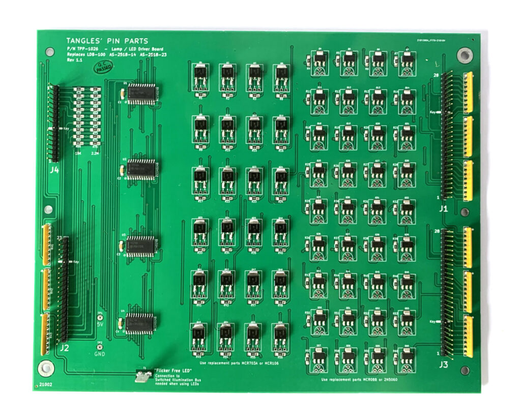
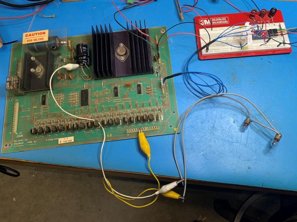
The Bally AS-2518-22 Solenoid driver board (SDB) can be put through a test regime using an Arduino. The heart of this driver board is the 74145 4-to-16 line decoder. In this project, I developed a simple testing rig using an Arduino to test all of the “Momentary Solenoid” drive components.
Parts Used:
Arduino Pro Mini (clone)
USB Serial programmer for Arduino
0.1” molex pins
5-Way 0.1” Molex shell
24AWG hookup wire
Some 0.1” jumper wires to connect power.
Alligator leads
2 x #44 bulbs
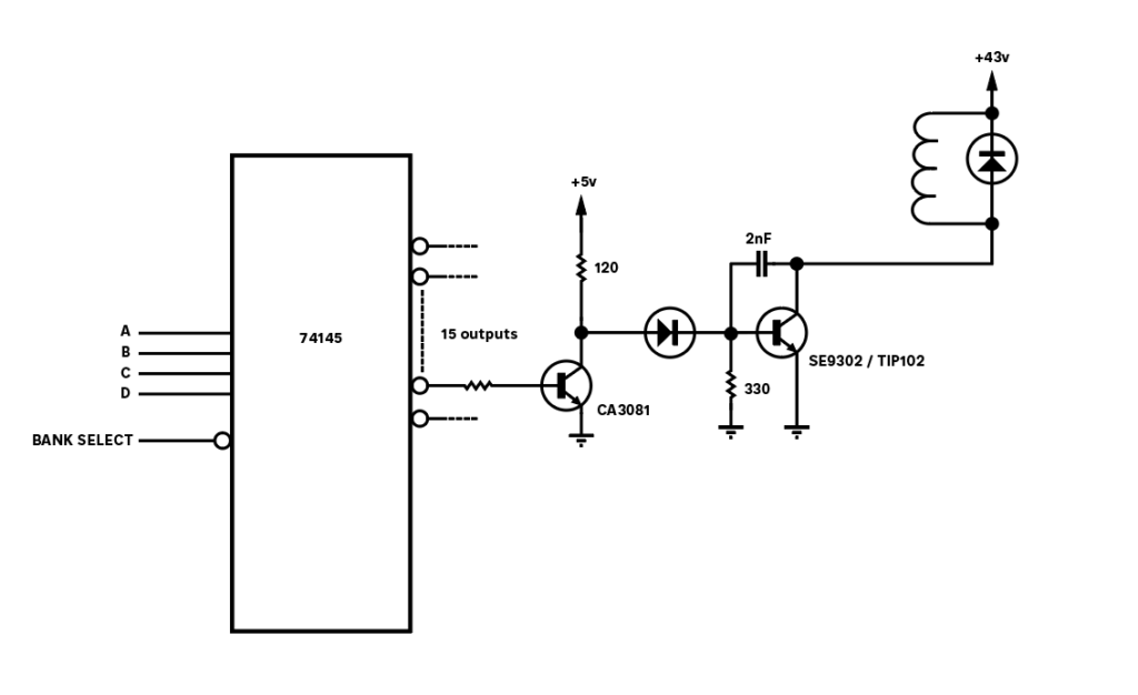
In this design, the Arduino sets up a binary signal (on PB0-3) driving the A,B,C and D inputs to the 74145. The Arduino then takes the CB2 line low causing one of the 15 output lines of the 74154 to go low.
Transistor Operation
At startup, the outputs from the 74145 are all high. This turns on the CA3081 transistors, depriving the main drive transistors of their base current and the solenoid output will be off.
When the appropriate binary input (A,B,C,D) is applied and then CB2 line pulled low, the 74145 will activate one of the 15 output lines. This active low output from the 74145 results in the associated CA3081 transistor turning off. With this transistor turned off, the main drive transistor can get its base current via the 120ohm resistor and the diode. This will turn the transistor on and a ground will be extended to the output line, powering the solenoid.
The 330 ohm resistor and the capacitor provide a small delay in turning off the solenoid. I suspect this is to ensure a clean turn off or a minimum on time.
Simplified Output Driver Operation
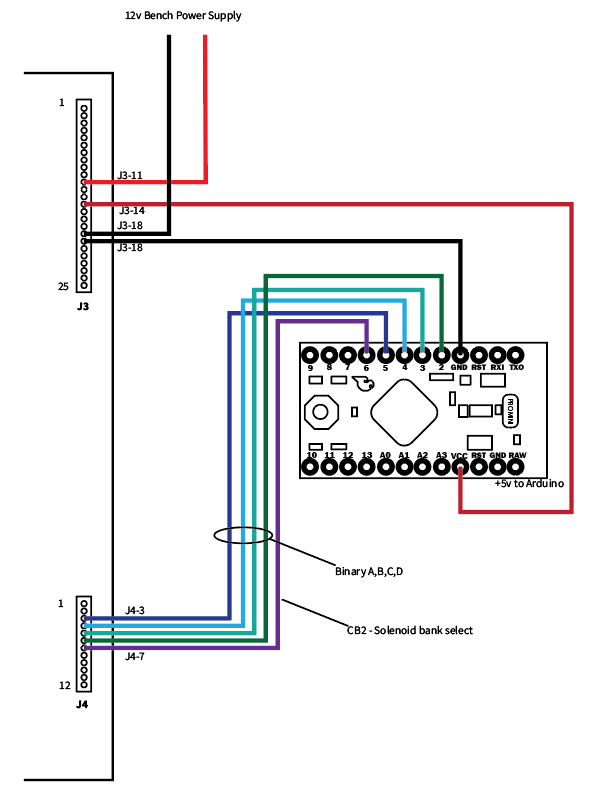
Connecting The Arduino
The Arduino needs to connect to the A,B,C,D, CB2 (Solenoid band select) and ground. In my setup, I supplied 12v DC to the SDB on J3-11 (12v) and J3-18 (GND). I then was able to use the 5V output from J3-14 to power the Arduino.
It is important to note the this SDB has had the under board GND and 5V wire modifications performed. Without these you will need to jumper TP3 to TP2 to power the digital parts of the SDB.
/*
 * 17-APR-2020
 *
 * Test rig for driving the Bally AS-2518-22 Solenoid Driver
 *
 * This program will provide inputs to the 74154 via the J4 connector.
 *
 * Author:  Malcolm Byrne
 *
 */

#define DATA_A 2      /*    Momentary Solenoid Data A    J4-6  */
#define DATA_B 3      /*    Momentary Solenoid Data B    J4-5  */
#define DATA_C 4      /*    Momentary Solenoid Data C    J4-4  */
#define DATA_D 5      /*    Momentary Solenoid Data D    J4-3  */
#define PIN_CS 6      /*    Solenoid Bank                J4-7  */


void setup() {
  // put your setup code here, to run once:
  pinMode(DATA_A, OUTPUT);
  pinMode(DATA_B, OUTPUT);
  pinMode(DATA_C, OUTPUT);
  pinMode(DATA_D, OUTPUT);
  pinMode(PIN_CS, OUTPUT);
  pinMode(LED_BUILTIN, OUTPUT);


  /* Initialize the 74154 with 1111 (out put 15) */
  digitalWrite(DATA_A, HIGH);
  digitalWrite(DATA_B, HIGH);
  digitalWrite(DATA_C, HIGH);
  digitalWrite(DATA_D, HIGH);

  digitalWrite(PIN_CS, HIGH);
  delay(20);
  digitalWrite(PIN_CS, LOW);
  delay(20);
  digitalWrite(PIN_CS, HIGH);


}

void loop() {
  int i;

  for ( i=1; i<16; i++) {
    solenoid_activate(i);
    strobe();
    delay(100);
    strobe();
    delay(100);
  }

}


void strobe() {
  int on_time = 300;  /* Milli Seconds */

  digitalWrite(PIN_CS, HIGH);
  digitalWrite(PIN_CS, LOW);
  digitalWrite(LED_BUILTIN, HIGH);

  delay(on_time);
  digitalWrite(PIN_CS, HIGH);
  digitalWrite(LED_BUILTIN, LOW);
}

void solenoid_activate( int i ) {
  /* Activate solenoid number  1 to 15 */
  int A,B,C,D;

  if (i<1) return;
  if (i>15) return;


  if (( i & 0b0001) > 0) {
    digitalWrite(DATA_A, HIGH);
  } else {
    digitalWrite(DATA_A, LOW);
  }

  if (( i & 0b0010) > 0) {
    digitalWrite(DATA_B, HIGH);
  } else {
    digitalWrite(DATA_B, LOW);
  }

  if (( i & 0b0100) > 0) {
    digitalWrite(DATA_C, HIGH);
  } else {
    digitalWrite(DATA_C, LOW);
  }

  if (( i & 0b1000) > 0) {
    digitalWrite(DATA_D, HIGH);
  } else {
    digitalWrite(DATA_D, LOW);
  }
}
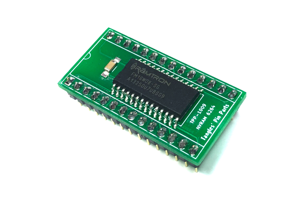
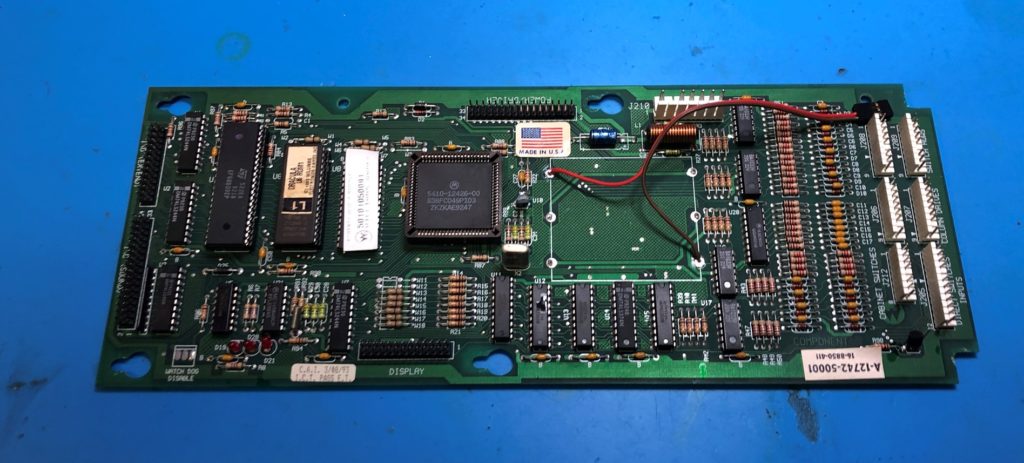
I’ve started installing Tangles TPP-1009 NVRAMS in all my Williams machines.
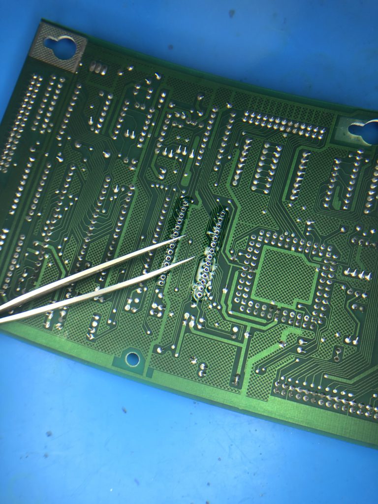
Installation of an NVRAM module into a Williams WPC board should be regarded as an operation suitable for people with advanced soldering skills only. The WPC circuit board do not have sockets on the 6464 memory and thus de-soldering is needed. Add to this the tiny hair-line traces on the WPC PCB, extra care is needed to ensure traces are not broken or damaged.
I’ll present here the tips and techniques I use, but rest assured these are better guides available for this advanced procedure.
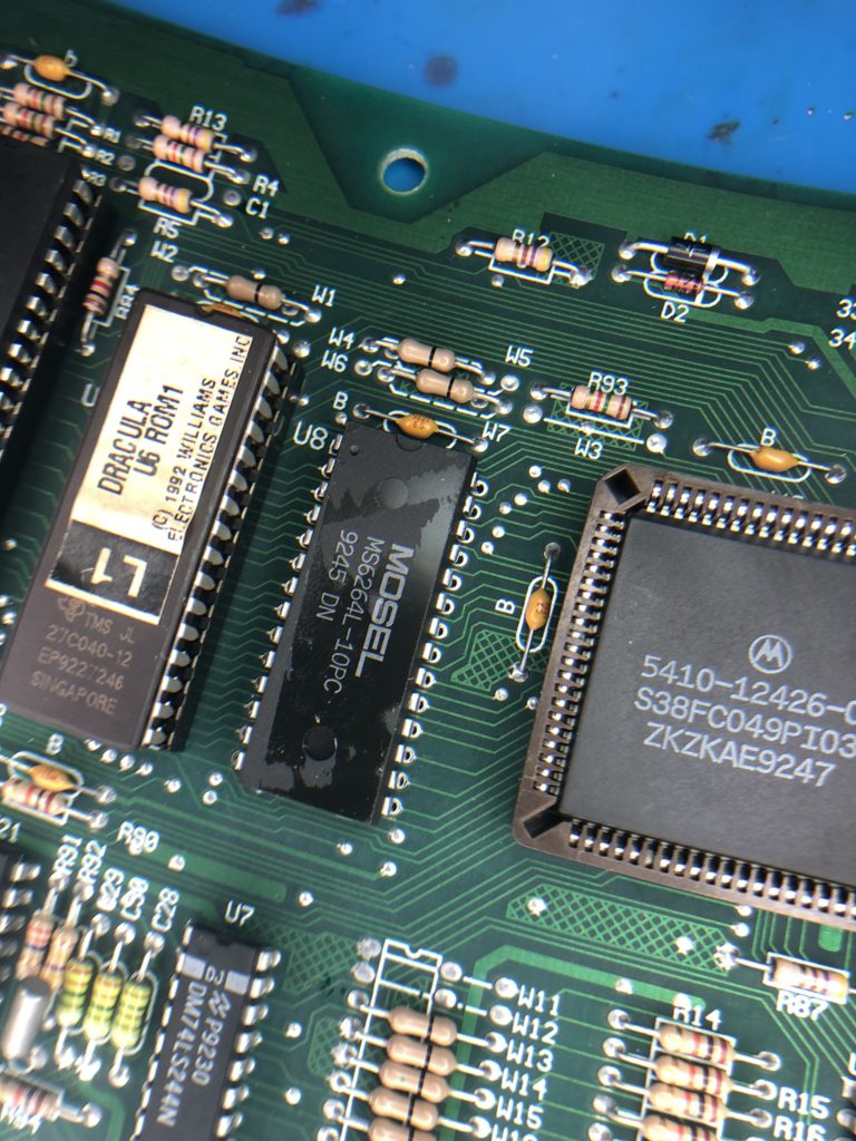
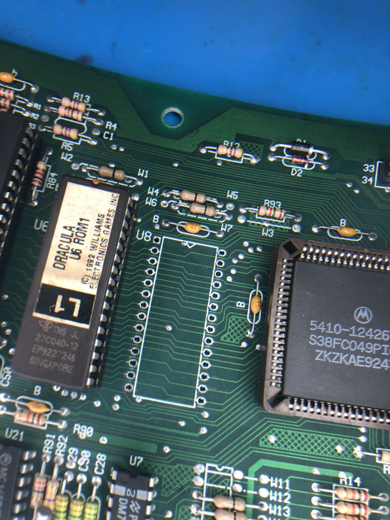
The 6264 RAM chip is located next to the rectangular PLA chip. It is typically covered with a warranty-void-if-removed sticker.
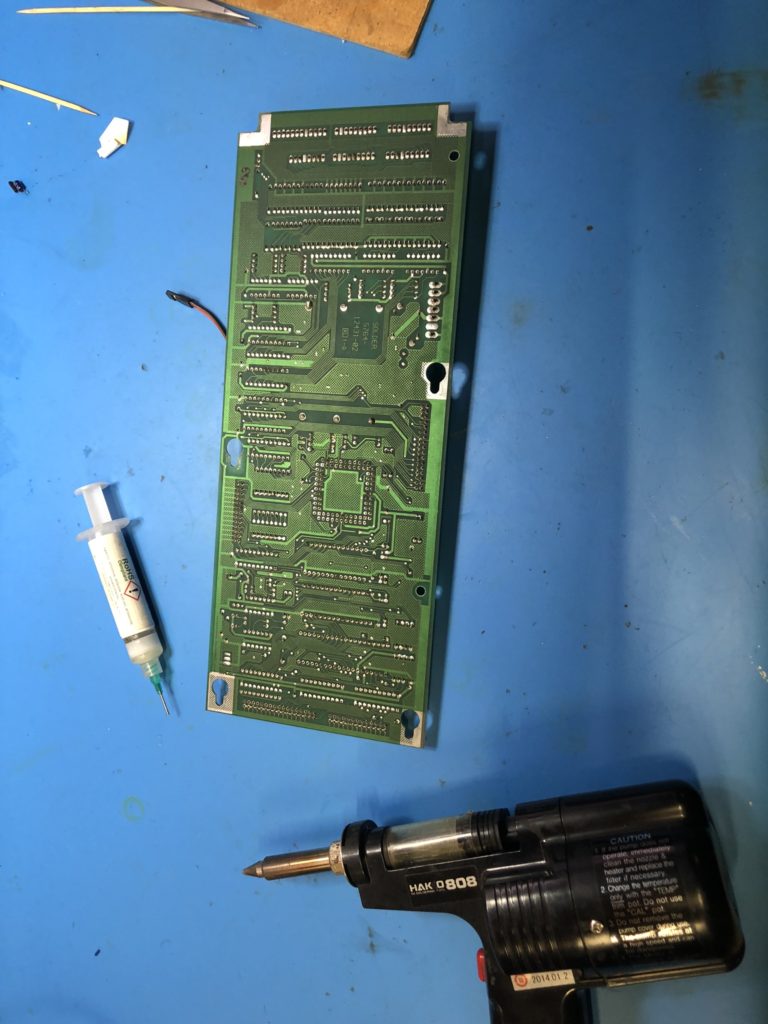
When de-soldering, I use a Hakko 808 de-soldering tool. Ensure you have the temperature of this tool turned down relatively low and high temperatures will lift the fine traces very quickly. I suggest 300 deg C.
I de-solder with the aid of a good quality gel flux. I prefer non activated flux as it is safe to leave some residue on the PCB. (Assume your cleaning efforts are not going to be perfect.) I use ChipQuik SMD291 flux.
When de-soldering, use light pressure and try not to let the tool tip press against the pad.
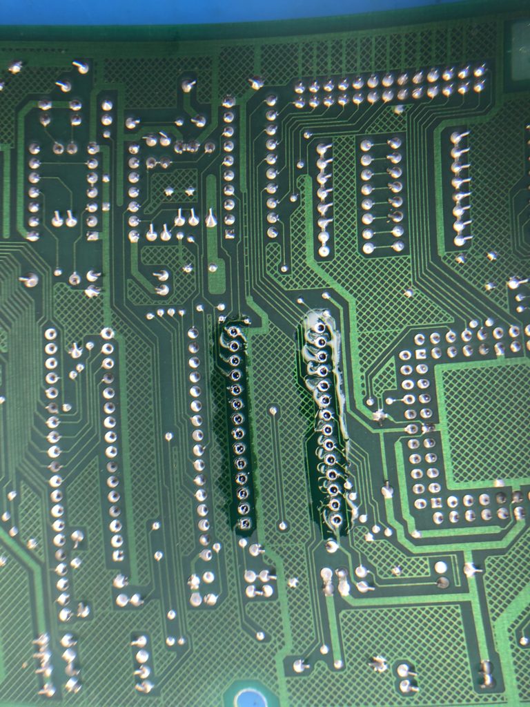
When de-soldering, use a circular wiggle motion as you activate the suction trigger. This helps remove solder from all around the pin.
When de-soldering allow enough heat up time before suction is applied. Ensure the solder is well and truly molten on both sides of the PCB.
After all pins are de-soldered, inspect all holes with a magnifying glass. Inspect both sides of the board to ensure all the solder has been removed.
I use tweezers and individually wiggle the chip ping to determine if they are still stuck to the sides of the through-hole plating. As you wiggle a pin you may hear a tiny cracking sound as the pin breaks free of the side-wall.
When all pins feel loose, gently start to wiggle the whole chip whilst watching the pins on the underside of the board. I am looking to identify any pins not moving when the chip is wiggled. These pins may need to be wiggled with the tweezers more or de-soldered a second time.
If I need to de-solder a second time, I first add solder to the pin. De-soldering works best when there is plenty of solder to remove. It works poorly when there is only a residual amount of solder in the joint.
When the chip is truly de-soldered, it should come out of the board with little pressure. NEVER pry the chip from the board!
When the chip is removed, carefully inspect the top and bottom of the PCB to ensure no damage has been made to the traces.
Clean the top and bottom of the board with isopropyl alcohol.
I apply a light smear of flux to the top side of the board. This flux will help the solder to flow from the board underside to the topside and adhere to the pad on the topside of the board.
Install a 28 pin socket. Ensure the notch on the socket matches the notch on the PCB silk-screen.
Solder the socket from the underside of the board. Ensure your soldering iron is not too hot. I set my iron to 300 deg C. This is a little lower than I normally use (320C), but is necessary to ensure the tiny traces are not cooked too much and lift from the board.
When soldering, I allow the pin to heat up. I apply solder. Then I wait until I can see the solder level dip (drop) as it flows to the top side of the PCB. I then add a small amount more solder. All of this should take place in less than 2 seconds.
When all pins are soldered, I carefully inspect the board underside.
I flip the board over and inspect the top side to be sure solder has flowed from underneath to the top side. This is easily seen when using a turned pin socked (round holes), but can still be seen if you are using a typical double wipe socket.
When I am happy with the soldering, I use a continuity tester and beep out every pin of the socket. I do this testing from the top side of the board.
Most pins are easy to beep as they go to a similar pin on the neighbouring EPROM.
Some pins are difficult to beep as they go to pins on the PLA.
Remove the old battery holder or wires if a remote battery was installed.
It is time to clean the top and bottom of the board with isopropyl alcohol to remove any flux residue.
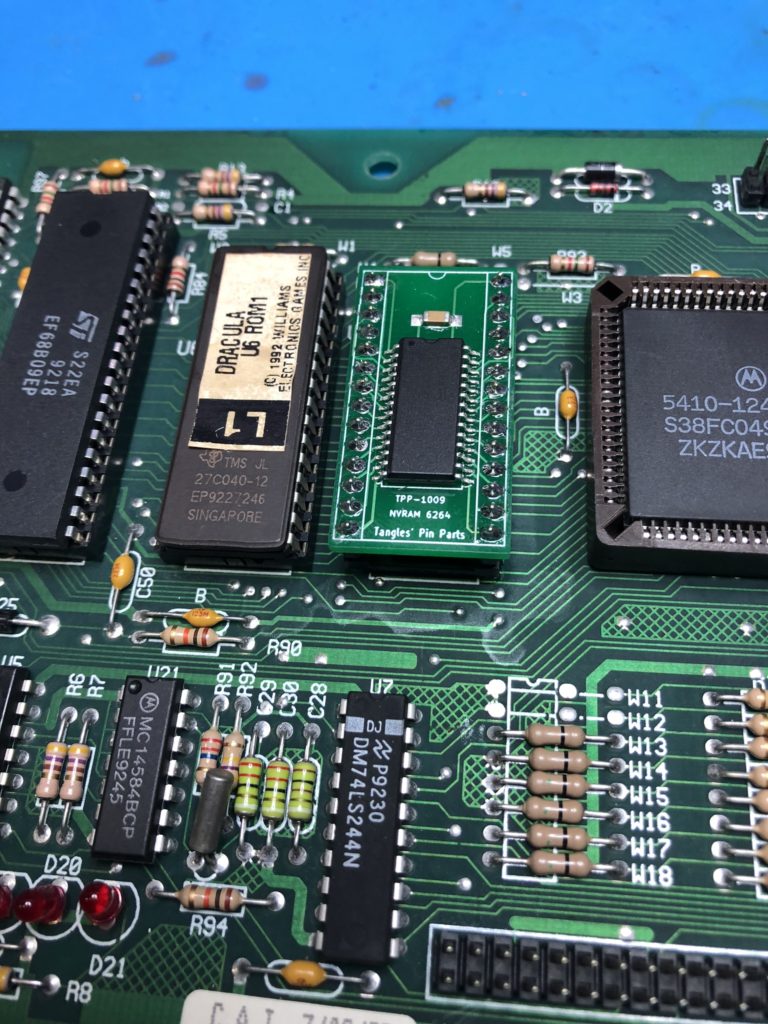
The TPP-1009 NVRAM can be inserted into the socket.
CPU board out of BSD. Ready for an NVRAM upgrade.De-soldering gun and tube of flux ready for the extraction First pass of de-soldering. I use plenty of flux! You can see clearly down each hole.Inspect each hole from the top side to ensure all the solder is gone. NEVER pry the chip out!Use tweezers to test each pin is free and not adhered to the side wall of the hole.The old RAM chip now comes out without any resistance.New socket installed. All pins beeped for continuity. TPP-1009 NVRAM can now be installed.
Owners of the 1995 Bally – Theatre
of Magic (ToM), may know of the problem relating to the Trunk getting “locked
out”. This problem has been well
documented over the years and indeed a couple of solutions exist as hardware
and software modification to alleviate the problem.
The fundamentals of the
problem are a bug in the game’s firmware. This bug will put the trunk into a
locked out state if the trunk eddy sensor receives a “hit” whilst the trunk is
in motion. Once locked out, the trunk will
not be allowed to move until the game is powered off.
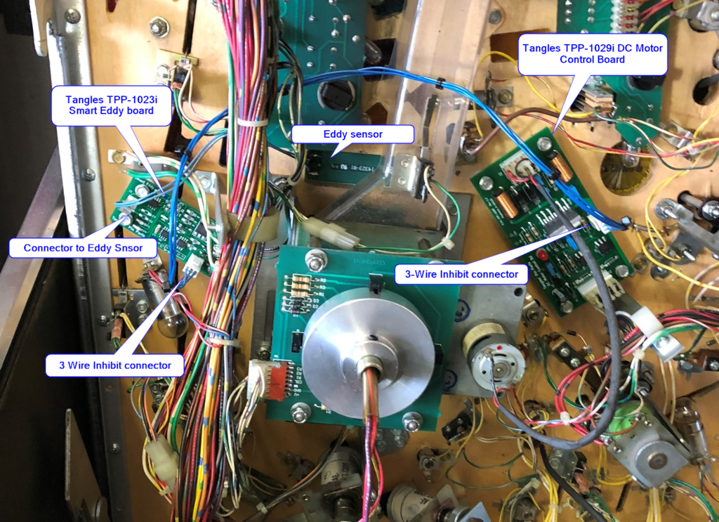
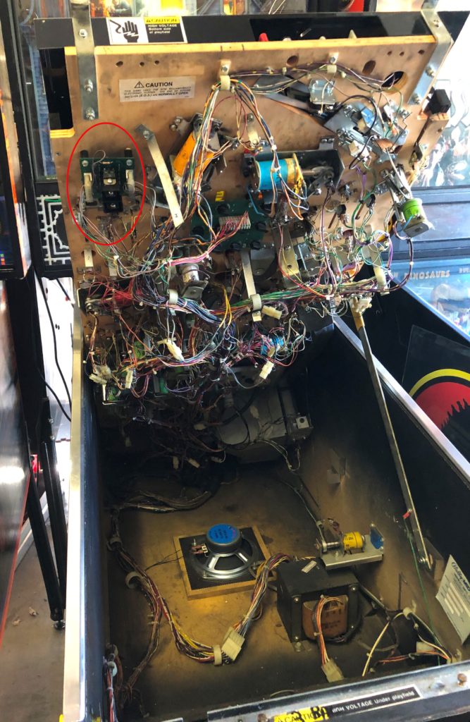
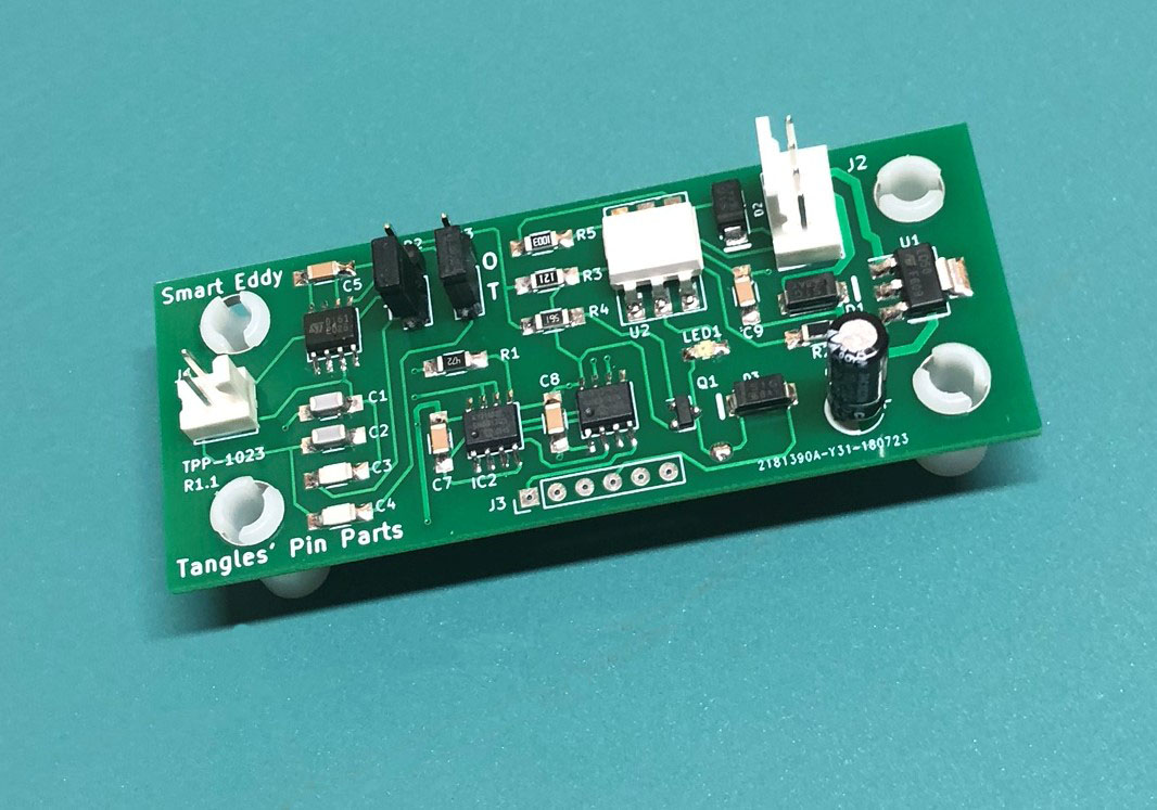
Having designed and
manufactured the Tangles’ Smart Eddy board (TPP-1023), I saw an opportunity for
this problem to be addressed in the Smart Eddy firmware. A new Molex plug was added to the Smart Eddy
to receive a signal from the Motor Control board. Using this communication, the Smart Eddy
board will refrain from sending eddy switch hits whilst the motor is running.
The signal connection into
the Smart Eddy may come from the original A-16120 or from the Tangles TPP-1029i
DC Controller board.
I propose this solution for ToM owners who are considering upgrading their eddy sensors to Smart Eddy boards, as the trunk fix can be piggy-backed onto this upgrade with little additional effort.
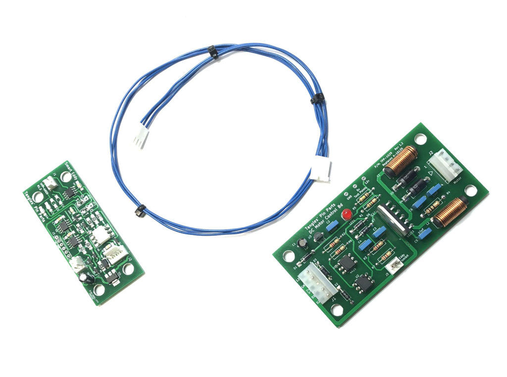
1 x TPP-1023 – Tangles’ Smart Eddy board – with
inhibit feature
1 x TPP-1029 Tangles’ DC Motor Control Board – with inhibit feature
1 x 3 wire cable ( 0.1” plugs –
560mm long)
Install the Smart Eddy Board (replacing the trunk eddy board).
Connect the 2 pin Eddy sensor.
Connect the 4 pin power/signal connector.
Install the DC Motor Driver board (replacing the original)
Connect the trunk motor to the 4-way header.
Connect the power/signal to the 5-way header.
Install the 3-Wire “inhibit” cable from Smart Eddy to the DC Motor Board.
Route the 3-wire cable under the wiring loom to stay clear of trunk opto.
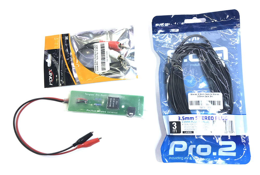
Parts for Tangles’ Trunk Fix (Theatre of Magic)Smart Eddy wired into a ToM with Trunk Fix options.
OPTION2 – MODIFIED DC MOTOR BOARD A16120
This option for experienced
repairers only.
Parts:
1 x TPP-1023i – Tangles’ Smart Eddy board – with inhibit feature. 2 x Molex 3 Position Rectangular Receptacle 22-01-3037 6 x Molex crimp pins 08-50-0032 3 x 560mm long 22AWG or 24AWG wire. 1 x Molex 3 Position Header 22-27-2031
INSTALLATION OPTION 2 • Install the Smart Eddy Board (replacing the trunk eddy board). • Connect the 2 pin Eddy sensor. • Connect the 4 pin power/signal connector. • Remove the A16120 board. • Drill holes for 22-27-2031 Molex header. • Install Molex plug. Glue or secure as needed. • Wire pin 1 to U2-Pin 5 • Wire pin 2 to U2-Pin 4 (ground) • Wire pin 3 to U1-Pin 5 • Re-install modified A16120 board. • Assemble / crimp 3-wire cable using 08-50-0032 pins and 22-01-3037 shell • Install the 3-Wire “inhibit” cable from Smart Eddy to the DC Motor Board. • Route the 3-wire cable under the wiring loom to stay clear of trunk opto.
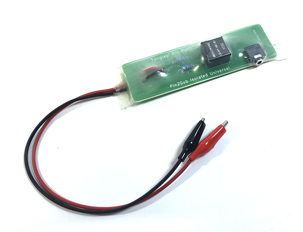
The Tangles TPP-1035 Pin 2 Sub Universal Isolated adapter is a safe and convenient way to tap the speaker output from your pinball machine and pass it to an active sub-woofer.
ISOLATED CONNECTION
The Tangles adapter uses a fully isolated circuit design. This isolation ensures no electrical connection is made between your pinball machine and the external active sub-woofer.
This is of vital importance not only in
reducing audio noise and hum, but to ensure that any fault, imbalance or
differences in mains power in the external speaker cannot jeopardise your
precious pinball electronics.
Isolation between devices is especially important with modern systems employing switch-mode power supplies.
UNIVERSAL COMPATIBILITY
The TPP-1035 is universally compatible with
pinball machines that have a cabinet speaker.
By nature of the
supplied alligator clips and the built in isolation transformer, the Pin2Sub
adapter can safely connect an active external sub-woofer to
Data-East, Williams, Bally, Stern or Gottlieb machines.
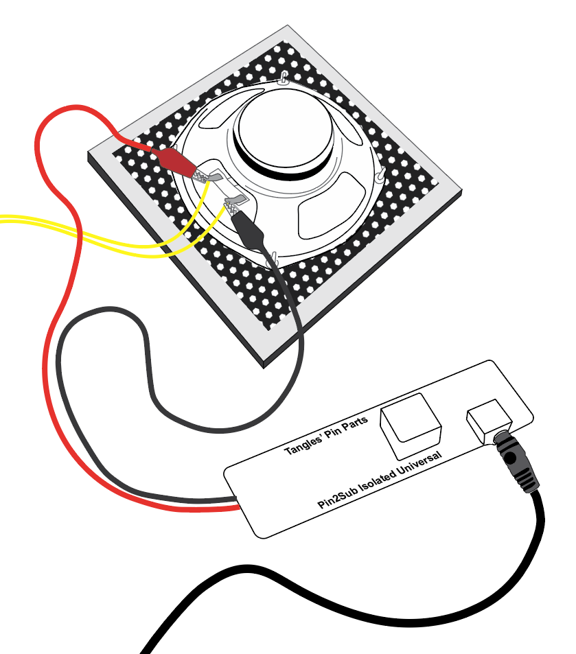
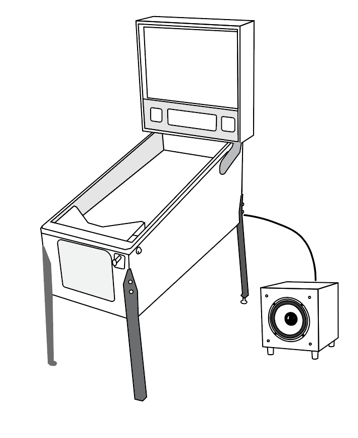
INSTALLATION
Remove the pinball glass
Lift the pinball playfield
Clip the Pin2Sub alligator clips onto the cabinet speaker terminals (Polarity does not matter)
Route the supplied 3mm AUX cable out of the pinball cabinet by removing one or two staples from an underneath vent / grill.
Plug the 3.5mm into the Pin2Sub adapter.
Position the Active sub-woofer beneath or beside the pinball machine.
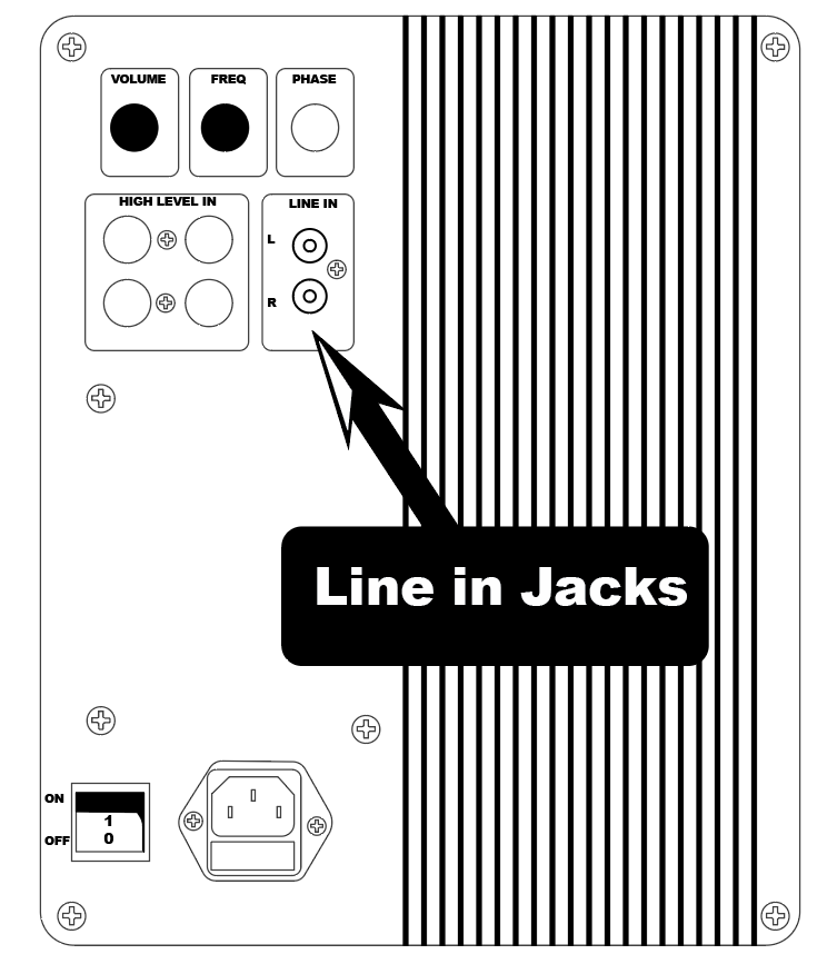
Plug the 3m AUX cable into the active sub-woofer. Use the supplied 3.5mm to RCA adapter if needed.
Reinstate the playfield and glass.
Power on the pinball and the active sub-woofer and adjust the sub-woofer volume using the volume control on the sub-woofer.
Pin 2 Sub Adapter Clips onto the speaker terminals of the cabinet speaker. Position the Active Sub-woofer Next to or underneath the pinball machineTypical Active Sub-Woofer panel, showing LINE IN jacks. Pin 2 Sub is supplied with a 3m AUX cable and RCA adapter
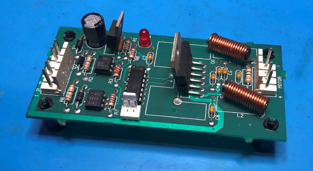
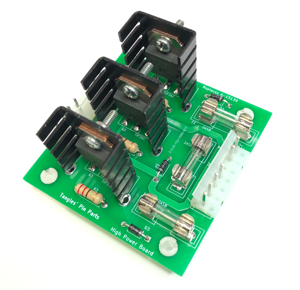
The
TPP-1030 board is redesigned replacement for the original A-15139 High power
driver. Whilst this board is generically
known as a high power driver board, it was used only on The Addams Family
machines to drive the three playfield magnets.
The
original board has been known to fail locking one or more magnets on. This can
lead to a burnt / scorched playfield… ouch!
Whilst
there is a 5 AMP fuse in-line with the original board, this fuse is across all
three magnets and typically does not blow when there is a single failed driver
transistor and one of the magnets is permanently activated.
The
recommended fix for this situation is to add individual (smaller valued) fuses
to the 3 magnet circuits. This can now be done neatly and easily with this
redesigned board featuring 3 on-board fuses.
Installation
is a snap, fits original mounting holes and original Molex connectors.
Replacement should take only a few minutes.
This board ships with 4 nylon mounts, 3 x 2A fuses installed and 2 spare fuses.
INSTALLATION
Warning: High voltages are present inside the pinball machine. Ensure the power is off and the mains cable is disconnected before you commence work.
Ensure power is off to the machine.
Remove the playfield glass and raise the playfield.
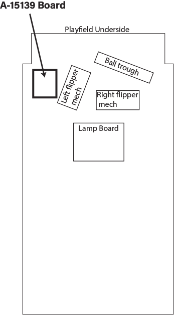
Locate the existing A-15139 board adjacent the left flipper mechanism
Remove two connectors (7-way and 8way)
Remove original board.
Install TPP-1030 board using original screws.
Reconnect two connectors
FUSE REPLACEMENT
The TPP-1030 uses three 5 x 20mm 2A slow blow fuses. A suitable replacement part is the Littelfuse part no: 0213002.MXP
BOARD LOCATION
Photo – under playfield showing location of A-15139 board
Replacement for A-18543-1, A-18543-2, A-18543.1-2 and A-16922
Smart Eddy (TPP-1023) is a re-designed “Eddy” proximity detector compatible with the games “Theatre of Magic”, “Star Trek – The Next Generation”, “Scared Stiff” and “Road Show”. The Smart Eddy board has an auto calibration feature that automatically adjusts the detector circuit each time the machine is turned on. This amazing auto calibration feature will free operators and owners from the tyranny of sensor adjustments that plague these games. Aging boards, playfield vibration and shaker motors all conspire to making the original boards a troublesome item.
The TPP-1023 board is a drop in replacement and amazing upgrade to the original boards. Matching the electrical and screw mounting* characteristics of the original parts, this re-designed unit can be installed easily with little fuss.